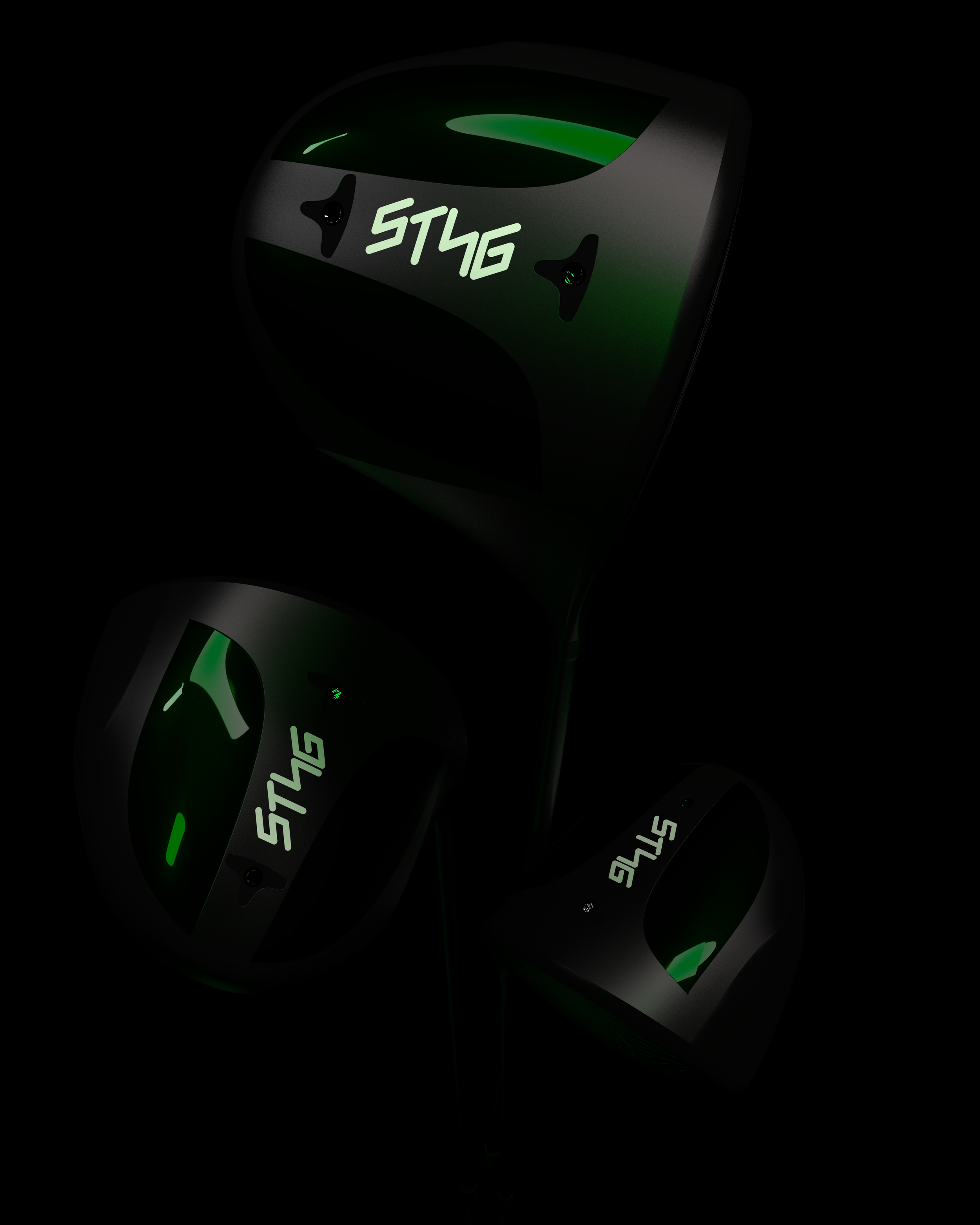
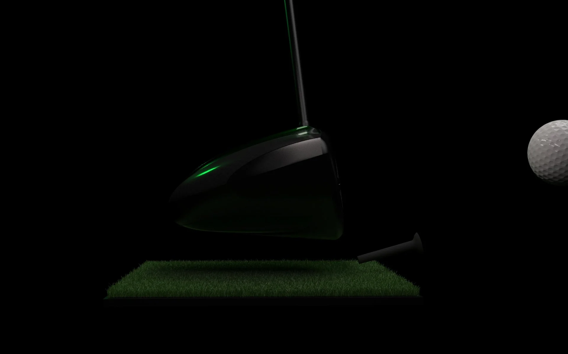
STNG Golf Driver
An independent, self-directed technical investigation into golf driver designs.

Why
I wanted to challenge myself with a highly technical product where performance could be tested, measured, and improved through iteration. Design decisions are validated through data outcomes — not preference or aesthetics alone.
Golf Intention
A golf driver presents a challenge because it is a tightly constrained, physics-driven design system where small geometric changes can significantly impact results.
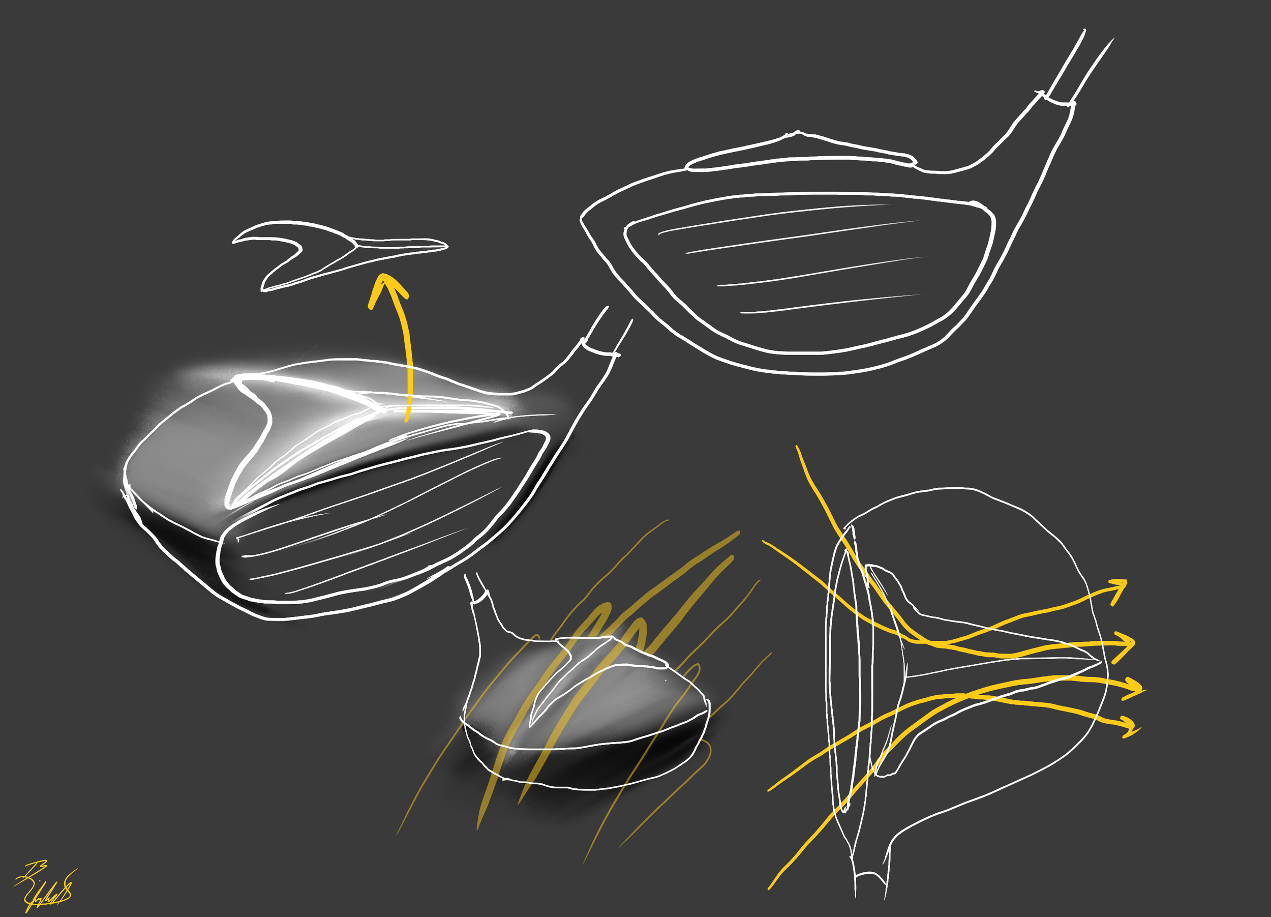
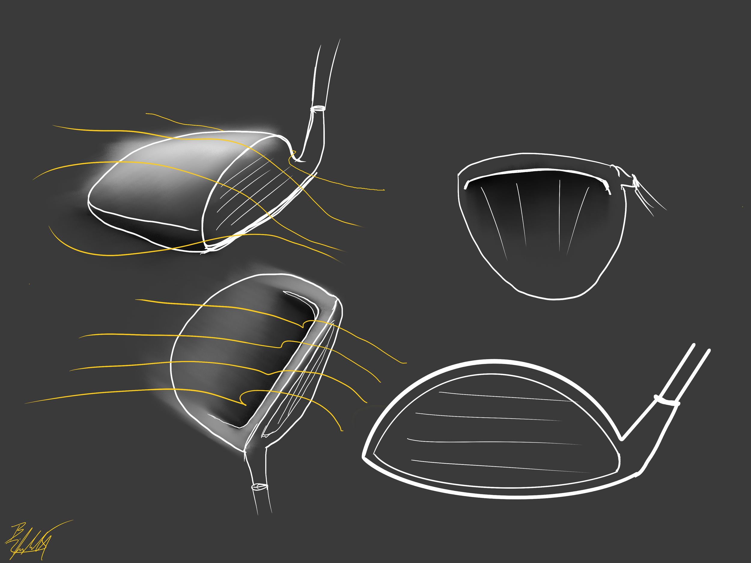
Concept #1:
Fin-like crown structure to control turbulence and guide airflow.
Physics Goals Addressed:
Minimize Kinetic Energy Loss: Reduces drag by controlling airflow separation.
Turbulence Management: Directs air in a stable, narrow wake.
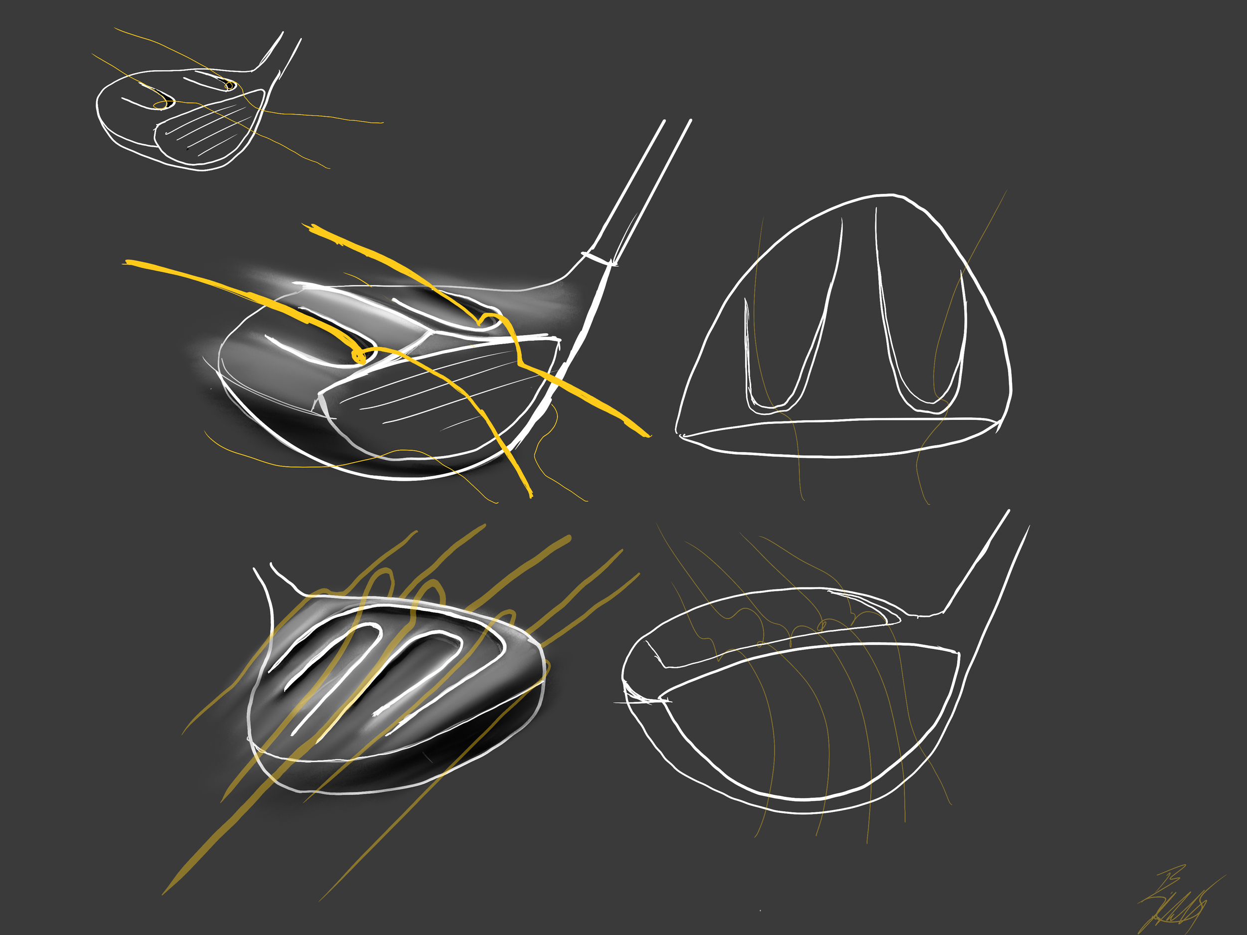
Concept #3:
Curved crown & flat sole for minimal resistance.
Physics Goals Addressed:
Flow Direction: Air efficiently glides around all sides of the clubhead with an air pocket on the bottom to maintain attached air.
Airflow: Reduce pressure drag, reduce turbulent swirls, increase clubhead speed.
Research → Sketches
Key Principles
-
Reducing drag allows club to accelerate efficiently through swing
-
Stabilizes off-center hits for better forgiveness
-
Target high launch and low spin for max distance
-
Narrow air wake and smooth airflow minimize resistance
Concept #2:
Small pockets on the crown to maintain attached airflow, reduce drag, and control separation just after the face.
Physics Goals Addressed:
Flow Attachment: Keeps airflow attached to the surface, reducing resistance.
Transition Control: Smooths airflow transition from face to crown.
Launch Consistency: Supports predictable ball launch.
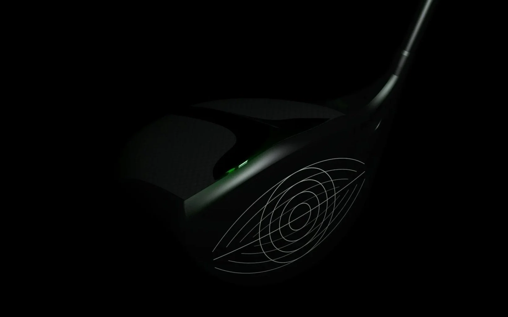
Concept 1 was ultimately chosen because its geometry may support predictable airflow patterns while minimizing the risk of excessive drag, all within USGA regulations.
Potential aerodynamic concerns with concept 2 included: possible high-drag recirculation zones, dead air pushing airflow away from the clubhead, or premature airflow separation.
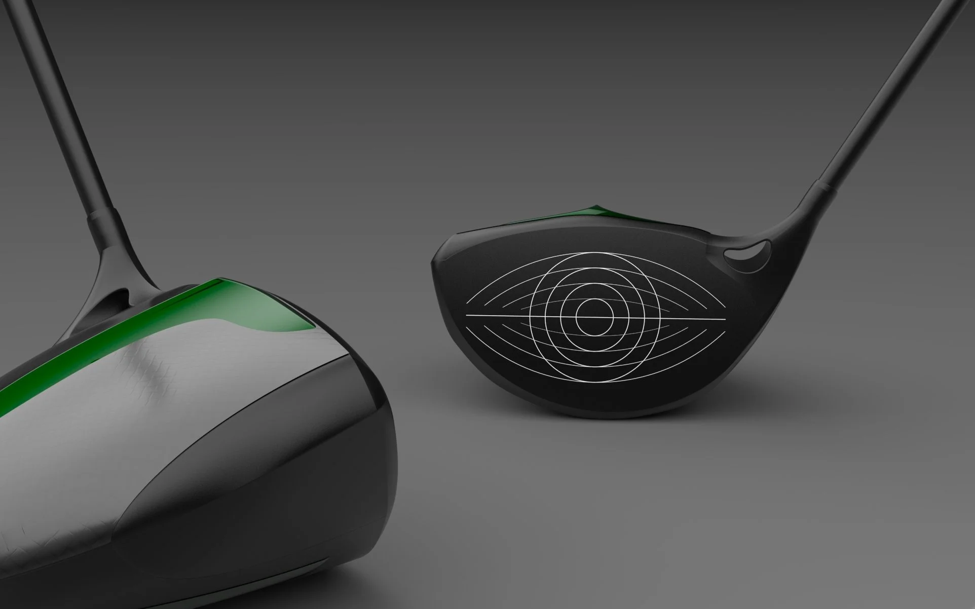
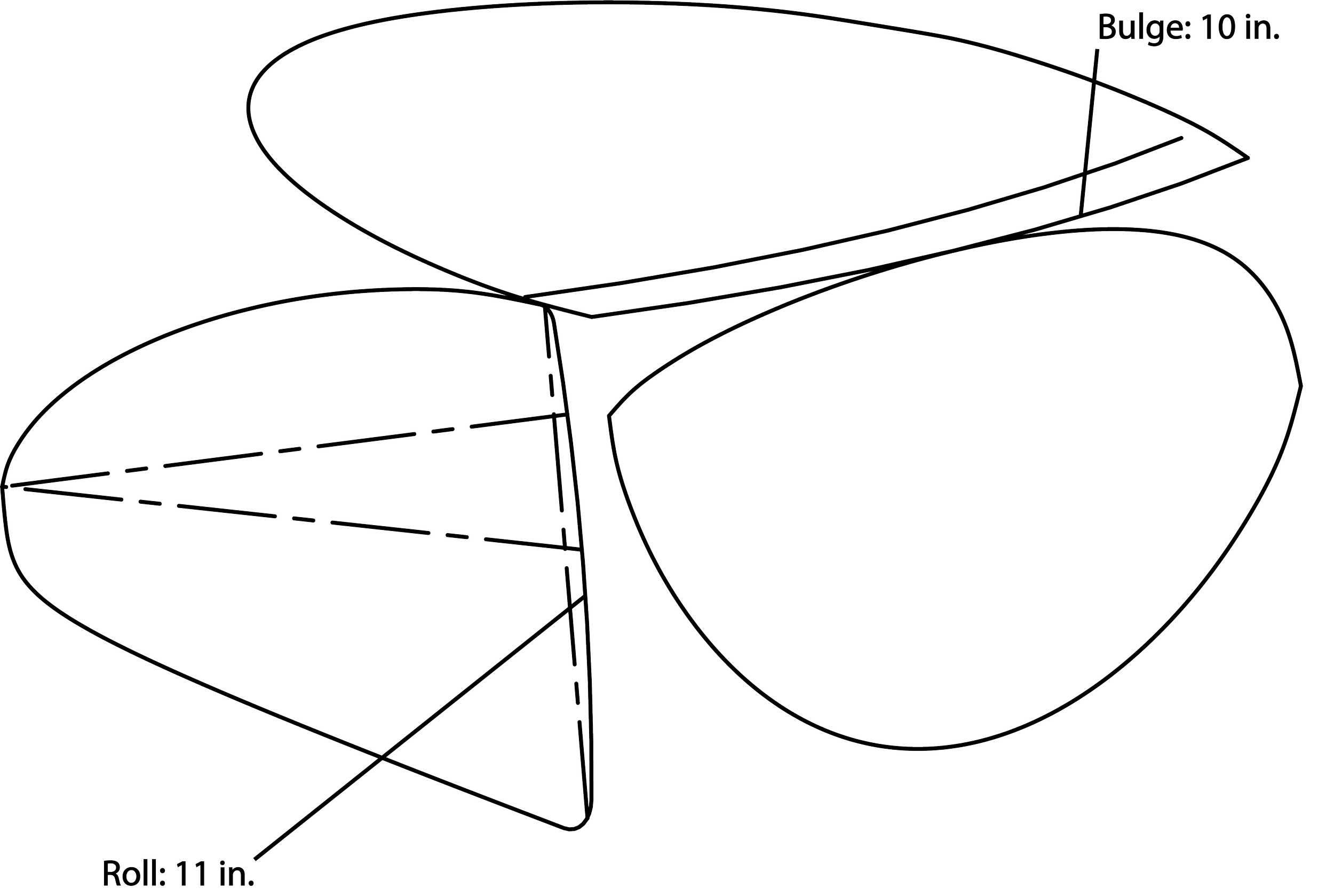
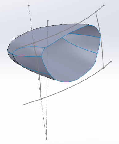
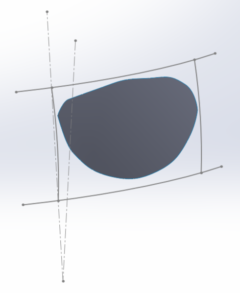
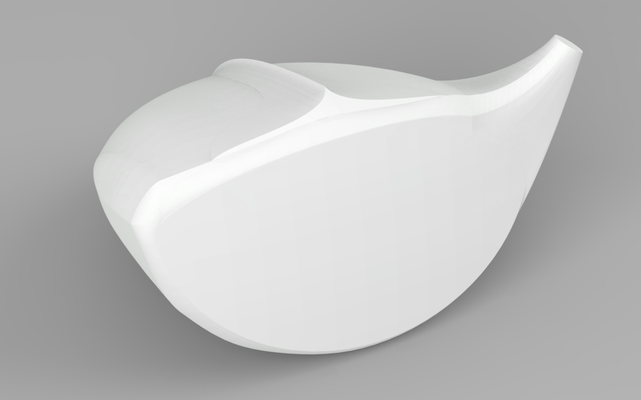
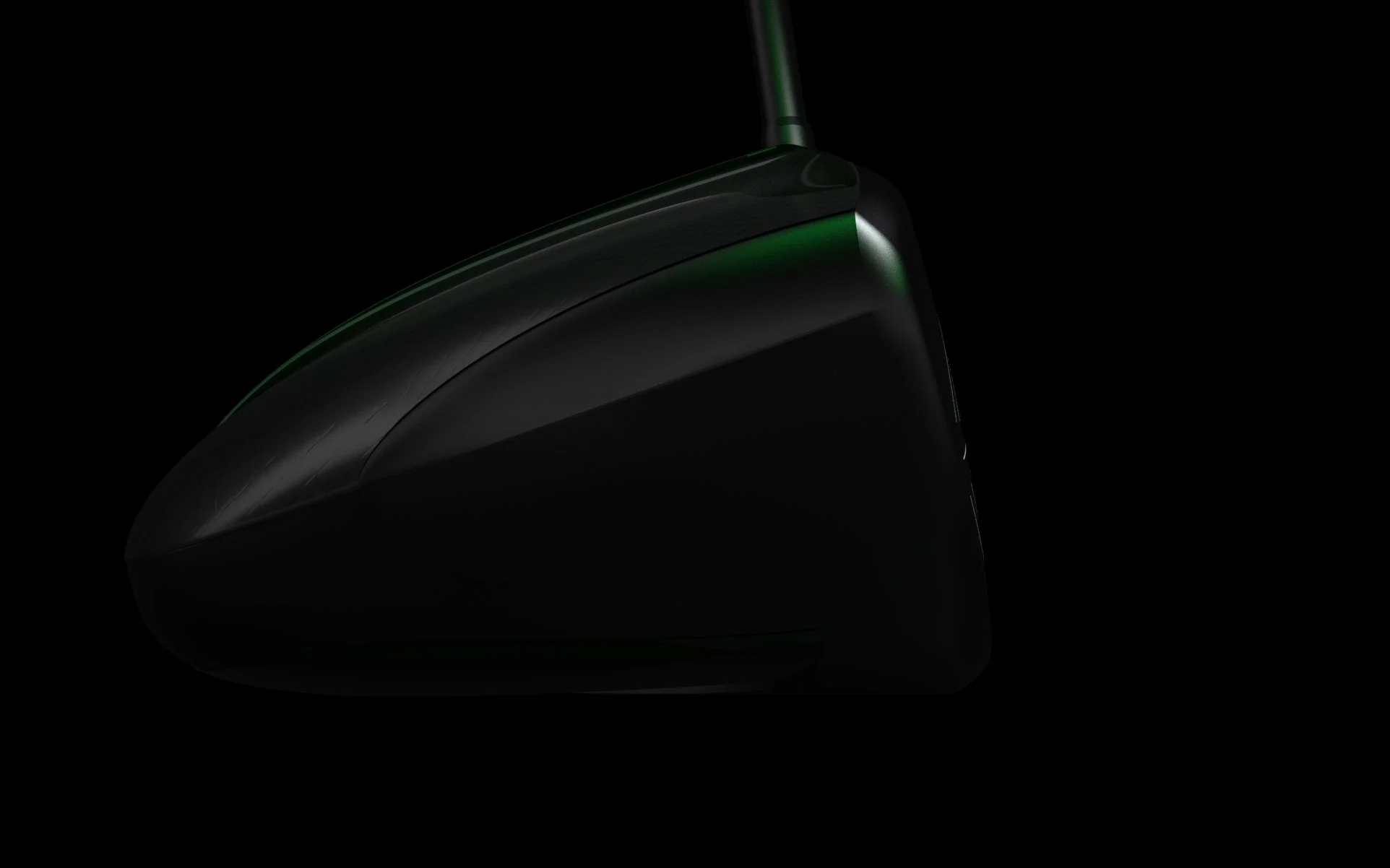
CAD
Using SolidWorks surface modeling tools, I replicated Concept 1 while ensuring all physical parameters and USGA legal restrictions were met.
Physical Considerations (Design Parameters):
Roll: 11 in.
Bulge: 10 in.
Loft: 10.5°
Weight Distribution: Optimized for MoI and balance
Groove Shape: must be U-shaped or square-shaped
Legal Considerations (USGA):
Coefficient of Restitution (COR): ≤ 0.83 (ball leaves the face at 83% of the clubhead speed)
Maximum Clubhead Volume: 460 cc
Club Length: Maximum 48 inches
Groove Dimensions: Groove width ≤ 0.035 inches, Groove depth: ≤ 0.020 inches

Weight Component Feature coming soon…
A weight on the toe of the driver helps raise moment of inertia by moving material away from the axis of rotation.
These weights are swappable for the golfer to find the best weight for them.

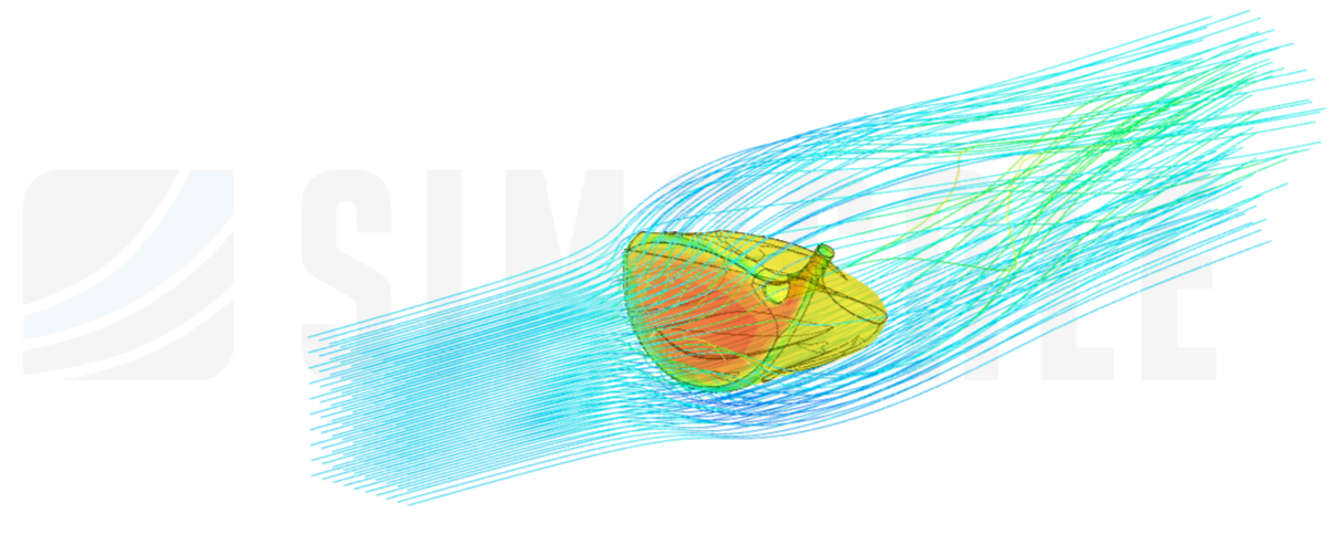
*Simulation done on SimScale*Aerodynamic Analysis
Goal
Learn how outer alterations to a golf driver can alter airflow patterns, and reveal opportunities to manage drag and understand club aerodynamics.
Simulation Details
Air Speed: 45 m/s
Simulation type: Incompressible CFD, steady-state
* Simulation is strictly linear. Natural curvature of golf swing was not tested*

*Simulation done on SimScale*The aerodynamic simulation revealed that the design did not improve airflow attachment over the crown as initially intended. Most of the airflow separated shortly after the face, indicating that the geometry was not effectively guiding air along the top surface.
While this iteration did not achieve the desired aerodynamic performance, the simulation provided valuable insight into how air behaves around a driver head. The results clarified which geometric features contribute to early separation and highlighted areas for refinement in future iterations.
And I plan on doing future iterations…